TDK RF Solutions
EMI EMC EMF Testing Report
TDK RF Solutions
    • Get A Quote >
      • New call-to-action

    TDK RF EMC Chambers

    TDK RF Solutions EMC chambers have solved the problems associated with both outdoor and conventional indoor measurement facilities. Their chambers employ their own high-performance radio weave-absorbing materials, carefully selected to match the test requirements

    TDK RF EMC anechoic chambers are complete turn-key systems which can be put into use immediately. Their performance has been thoroughly verified to correspond well with the values obtained for the very best open site testing facilities.
    Explore TDK RF EMC Chambers

    3m Compliant Semi-Anechoic Test Chamber Facility

    3m-compliant-semi-anechoic-chamber-325x250

    Our baseline semi-anechoic 3-meter chambers are designed to provide an optimal environment for radiated emissions and radiated immunity measurements.

    ANSI C63.4    Radiated Emissions
    CISPR 11, 12, 16, 22, 25, 32  Radiated Emissions
    IEC 61000-4-3   Radiated Immunity

    TDK’s standard configuration targets +/-3.5dB NSA and +5.5dB sVSWR performance. Our NSA, sVSWR, and Field Uniformity measurement results will provide unmatched reliability, repeatability, and the highest performance environment possible.

    Minimum Internal Working Space
    L 8.50 m  (28’-0”)
    W 5.00 m (16’-5”)
    H 5.50 m (18’-0”)

    RF Shielding Inner Dimensions
    L 9.00 m (29’-6”)
    W 6.00 m (19’-8”)
    H 6.00 m (19’-8”)

    External Dimensions with support steel
    L 9.30 m (30’-6”)
    W 6.30 m (20’-8”)
    H 6.65 m (21’-10”)

    New call-to-action

    10m Compliant Semi-Anechoic Test Chamber Facility

    10m-compliant-semi-anechoic-chamber-325x250

    Our baseline semi-anechoic 10-meter chambers are designed to provide an optimal environment for radiated emissions and radiated immunity measurements in full compliance with many industry standards such as ANSI C63.4, EN 50147-2, CISPR 12, CISPR 16, CISPR 22, SAE, and many more.

    With TDK’s history and experience as the original inventor of hybrid RF absorber technology (ferrite tile + foam RF absorber) and being the only test chamber company to manufacture both the ferrite tiles and the foam RF absorbers, we are in a unique position to warrantee the best possible anechoic validation performance values.

    With our standard configuration, we target +/-3.5dB NSA and +5.5dB sVSWR performance. You can rest assured our NSA, sVSWR, and Field Uniformity measurement results will provide you with unmatched reliability, repeatability, and the highest performance environment possible that exceed industry compliance regulations.

    Minimum Internal Working Space
    L 16.50 m
    W 9.00 m
    H 7.60 m

    RF Shielding Inner Dimensions
    L 18.50 m
    W 11.00 m
    H 8.60 m

    External Dimensions with support steel
    L 19.20 m
    H 11.70 m
    W 9.70 m

    New call-to-action

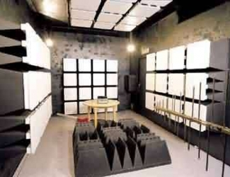
    Antenna Pattern Measurement Chamber

    TDK-antenna-test-chamber-325x250

    TDK has developed two standard antenna evaluation chambers for users’ antenna measurement system requirements. TDK’s Type A chamber is designed to provide the best performance in a moderately sized chamber. The Type B chamber is designed to provide optimized performance in a restricted size format. Both chambers utilize TDK’s one-of-kind polyethylene closed cell foam and oblique incidence absorber to provide superior performance over a broad frequency range.

    These chamber designs are suitable for modern and next generation wireless characterization, as well as stand alone antenna evaluations for such technologies as WLAN, BT, RFID, ETC, Mobile Telecom, UWB, SDARS, and others. The frequency range of use is from 800 MHz to millimeter-wave applications. Other frequency ranges can also be accommodated with different chamber configurations or absorber treatment.

     Features 

        • Stable physical and electrical characteristics for absorbing materials.
        • Compact size coupled with high performance.
        • Reduced specular activity based on oblique incident absorbers.
        • Optimized quiet zone available for different applications.
        • Closed cell absorbers for clean environment (no carbon dust).
        • Green manufacturing process: ISO 9001,ISO 14001 & RoHS compliant.
        • Applicable for Millimeter-wave testing up to 110GHz.
        • Bright work area with light reflective white caps.
    New call-to-action

    Compact Semi-Anechoic Chamber CAC-S™ (26 MHz - 18 GHz)

    TDK-CACS-2618-copy-325x250

    The TDK semi-anechoic EMC chamber CAC-S™, with a size of 7.5 m long, 3.0 m wide and 4.0 m high (24′-7″ x 13′-1″ x 9′-10″), is the most compact EMC anechoic test facility to perform radiated EMC measurements between 26 MHz and 18 GHz. A major advantage of this compact RF anechoic chamber is that it can be constructed within most industrial buildings and office areas.

    The space saving characteristics are obtained by the use of a particular EMC absorber installation technique which was invented and patented by TDK – the double layer technique. TDK ferrite tiles are mounted onto dielectric panels to cover the complete frequency range from 26 MHz to 1,000 MHz.

    By installing TDK IP-045 series resistive absorbers in selected areas of ceiling and walls, the frequency range can be extended up to 18 GHz. White end caps complete the absorbers and greatly improve the illumination levels inside the EMC anechoic chamber.

    CAC-S enables the user to carry out radiated immunity measurements in full compliance with IEC 1000-4-2 standard over the frequency range from 26 MHz to 18 GHz. 3 meter radiated emissions measurements can be performed at a fixed receive antenna height in the 30 MHz to 18 GHz frequency range. This makes the compact anechoic chamber (CAC-S) an ideal facility to test small apparatus.

    New call-to-action

    Interested in becoming Our Partner?